Technical > Ventilation

Section under repair
The ventilation system at Pleasley, as in all British collieries, operated on the exhausting principle, with the North shaft being the downcast and the South shaft the upcast. The ventilation air passed from the upcast shaft into a fan drift 30yd below ground level which carried the air to the fan-house complex located 65yd south-west of the shaft. For some reason the fan-houses were constructed a few yards to the south-east of the inter-shaft axis and the exact route the drift took below the surface is not known. On approaching the fan-house the drift split into two branches, each branch leading into a fan-pit up which the air ascended to the fan inlets. Shutters which could be raised and lowered were placed in the branch drifts at their junction with the fan pits and the fans could be changed over at any time without interfering with the ventilation of the mine.
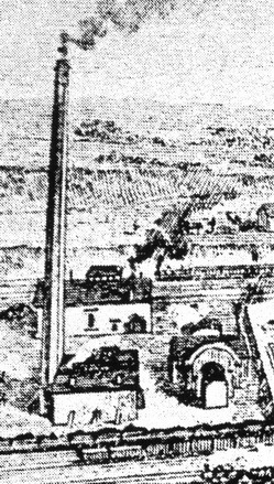
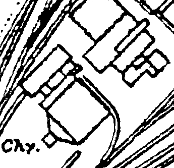
The fan-house complex was under construction when the 1875 1:2500 map was prepared and the two inlet-pits can be clearly seen. The ventilation was provided by two Waddle fans and in the 1899 map the fan discharge slots can be seen on either side of the engine house. The fan boilers and their chimney are also shown.

fan-house complex circa 1874 (JST)


fan-house complex circa 1899 (JST)
fan-house complex circa 1888 (JST)
The fans were 40ft in diameter with 14 ft inlets - the width of the vanes at the throat probably around 4ft and at the periphery maybe 16in. They were each driven by a single cylinder steam engine, 26in diameter and 48in stroke, the engine house being located between the fans. At 50 rpm and 2in water-gauge they circulated about 81,450 cubic feet per minute. Each fan was run for a month at a time, with the other kept in reserve.


Schematic layout of the main ventilation fans 1875 - 1900
The fan-engines were supplied with steam from their own boilers in a boiler-house located about 10 yds SW of the fan-house. Initially, there were probably only two boilers but in 1891 a bank of four 30ft x 7ft Lancashire boilers with 2ft 8in tubes were in use, providing steam to drive a dynamo for the newly installed electrical system as well as the fan. By the 1920s these had been replaced by four 30ft x 9ft ones. The feed water for the boilers was provided by a single no.9 exhaust injector supplied with exhaust steam from the fan-engine.

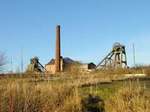
fan-house and boiler chimney circa 1916 (FoPP)
By about 1910 the two Waddle fans would have reached the end of their operational life. They were of an early, less efficient design and their capacity would no longer have been adequate for the expanding underground workings. In addition they possessed a serious disadvantage. The Coal Mines Act introduced in 1911 required that all mines ventilated by mechanical means should have facilities for reversing the air flow in case of emergency. The Waddle fans, however, were open-running and the configuration of their inlets and discharge would not be easy to modify.
(NB: when the fourth Stanton Ironworks colliery at Bilsthorpe was sunk a Waddle fan was installed there. This had a diameter of 15 ft with an inlet of 12 ft and was capable of circulating 300,000 cu. ft / sec. It was driven by a Bellis and Morcom V-twin engine developing 218 bhp at 180 rpm using steam at about 150 psi. In this case the design of the fan inlets included air reversing facilities)
In 1892 a Capell fan had been installed at Teversal Colliery as a replacement for the original Waddle fan which, after 24 years in use, was worn out - partially as a result of the presence in the airflow of steam coming from the underground haulage engines. Before the Waddle fan was removed a series of tests were conducted to compare the performances of the two types of fans. These tests suggested that there was little difference between the older Waddle fan and the new Capell fan but, not surprisingly, the test results were challenged by the designer of the fan, the Rev. Capell and his fan was eventually shown to be superior. Subsequently, some point between 1899 and 1915, the east fan at Pleasley was replaced by a 12ft diameter Capell fan driven by a 350 HP Bellis and Morcom high speed engine. This fan ran at 255 rpm and produced approximately 169,000 cubic feet of air at 6in water-gauge.
Photo to go here

Fan.house complex circa 1915 (JST)
Around 1917, work began on replacing the remaining Waddle fan with a 14ft diameter Walker Indestructible fan driven by a Walker high speed engine. This fan ran at 275 rpm and produced 190,000 cubic feet of air at 91/2in water-gauge.
Photo to go here
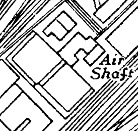
The 1916 1:2500 map shows a third air shaft closer to the South shaft and in the 1938 version it is still shown, but now with a building associated above it. This would have been a temporary fan for use during the construction of the two new fan houses. It was probably also used during the replacement of the Capell fan during the 1950’s modernisation and the lip of it could still be seen in 2010.


Intermediate air-shaft circa 1916 (JST)
Intermediate air-shaft circa 1938 (JST)
The Walker fan itself appears to have performed satisfactorily since it remained in service until closure. The high-speed engine, however, proved to be quite problematic and the manufacturers even resorted to removing the fly-wheel rim of the fan coupling as they attempted to improve its performance. Despite all their efforts it was replaced in 1923 by a 425 HP (? Mather and Platt ?) synchronous AC motor driving the fan by means of nineteen 1⅛in. diameter cotton ropes. The motor was located in the building adjacent to the fan that had been constructed in 1897 to house a new pair of dynamos. This motor was still in use as a stand-by in the 1960s - and probably remained so until the colliery closed twenty odd years later.
After the motor drive for the Walker fan was installed the fan boilers and chimney were dismantled and the boilers transferred to Silverhill colliery along with the Waddle fan itself. The Capell fan was then fed from the new main boiler range via a pipe range which ran along the front of the Power House and can be seen supported on brick pylons in the centre right of the next photo. The Bellis and Morcom engine had a constant trickle feed of live steam keeping it and the pipework warm and ready for operation .

Fan-house complex circa 1932. (FoPP/JST)
In the photograph above, the Walker fan evasée chimney is in the centre foreground and its electric drive motor was in the building to the left. The motor was located to the rear of the building with the fan pulley at the near end. The Capell fan is in the lower RH corner of the photograph. The building between the fans housed the high-speed fan-engines.
Photos to go here
As part of the 1950s modernisation the Capell fan was removed and a new main fan house constructed in its place. A 3.3 kV ???HP synchronous motor was installed which drove an powerfull aerofoil fan via a reduction gearbox. This gave 293,00 cfm at 11 in. water guage.
Photos to go here
In the 1960s when the main development face in the Piper seam, 400s, commenced operation close to the upcast pit-bottom, three axial-flow booster fans were installed to boost the ventilation for the distant NE faces working off of 200’s and 210’s loader gates. These were located in the RH gate of the old Deep Hard A-panel which now formed the main return airway for the workings on that side.
Map to go here
When the faces on A side in the Deep Hard were finished the booster fans were removed and a new set installed at the outby end of 400’s return airway in the Piper seam to improve the ventilation in the faces which were now re-entering the Deep Hard seam beyond the old B side workings. These gave 73,000 cfm at 13.6 in. water gauge.
Photo to go here
In the second half of 1977, preparations began for driving a roadway from the South pit-bottom to link up with the left-hand gate of a face in the Deep Hard seam which was working back towards the pit-bottom along the far side of East fault. In order to provide a fresh air supply for the heading a number of alterations were made to the ventilation system in the old roadways at the outby end of A-panel on the north-west side of the shaft-pillar
After production at Pleasley ceased and salvaging had been completed, the North shaft was filled and the South shaft converted to a downcast to supply air to Shirebrook colliery via the Deep Hard link.
TOP
Copyright © 2023 J.S. Thatcher
Page updated on:
11 Nov, 2023
at
05:24:42 PM
In case of problems contact: