
Section under development
Introduction

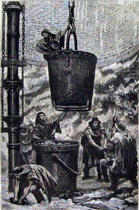
Shaft sinking scene circa 1875
The shaft would be bricked up as sinking progressed, with the brickwork built on a supporting ring known as a “bricking curb”. This was made of cast-iron or oak segments and rested on a lip of solid rock which would be removed as the brickwork was brought up from the next curb below.
Small amounts of water could be dealt with by bailing into the kibble (sinking bucket) but when larger feeders of water were encountered, sinking pumps had to be installed. The pump would be a bucket type operated by strong wooden spear-rods, usually pitch pine, connected to a steam engine on the surface. The pump body would be located several feet above the inlet, well out of way of any shot-firing.
Suspension chains were attached to crabs (winches) on the surface and allowed the suction pipe-work to be extended and the pump body to be repositioned as sinking progressed, the rising main pipe-work being supported at intervals on timber frames let into the shaft side.
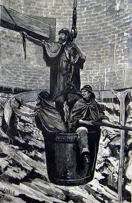
To handle water draining down the walls during the sinking, a temporary water-garland would be attached to the lowest curb and the water piped down to the pump inlet. Where more permanent drainage was required, a combined cast-iron bricking curb and water-garland would be installed.

Fixing a temporary water-garland circa 1875
In shafts where guide-rails were used, they were fastened to strong timbers (buntons, byatts, etc) located in cast-iron boxes let into the shaft walls as shown above.
To be continued
Copyright © 2023 J.S. Thatcher
Page updated on:
11 Nov, 2023
at
05:24:42 PM
In case of problems contact: