Technical > Boilers

Section under repair
Contents:
- > introduction
- > the boiler houses
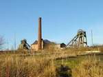
- > the chimneys
- > the boilers
- > the coal supply
- > the water supply
- > the ash disposal
Steam was used to power not only the winding engines, but also subsidiary engines driving the ventilation fans, the screens and electrical generators. The steam plant at Pleasley Colliery was based around the fire tube boiler. Originally, 8 Cornish and 8 Lancashire boilers were located in 4 ranges alongside the engine-houses, providing steam for the winders and the screens together with further small range of Lancashire boilers supplying steam for the fan engines.
1875 OS map and 1885 image to go here
In the late 19th (and for a good part of the 20th century) this type of boiler was the dominant form of steam raising plant for stationary engines throughout the world and many thousands were produced. They were transported from the manufacturer by rail as far as possible.

In 1873 the nearest suitable railway delivery point would have been at Mansfield 3 miles away and they would have completed the rest of the journey to Pleasley by road, probably using a steam traction engine. The main road travelling north towards Pleasley was on the opposite side of the town from the railway sidings and there must have been some interesting sights as these monsters threaded their way through the town centre.
There were many changes to the steam plant over the years reflecting increases in output capacity to cope with demand and in operating pressures needed for the more powerful winders. Improvements in boiler efficiencies and economies were incorporated whenever worn-out plant was replaced.
The highly respected local mining engineer, J A Longden, took an active interest in the economics of boiler operation and his appointment as Managing Director of the collieries quickly brought improvements at Pleasley. By 1891, Caddy tubular fire-bars, patented only five years earlier, had been applied to all the boilers increasing their efficiency and reducing the level of black smoke from the chimneys. They consisted of 1 in. x 41/2 in. hollow cast-iron bars with a smooth chilled face. They were formed around slightly flattened wrought iron tubes and were supported on a split bridge at the rear. Air traveling through the tubes was heated and this secondary air, discharged between the bridges, completed the combustion of any unburnt gases and helped eliminate smoke. By keeping the fire-bars cool the adherence of clinker was reduced and the primary air path between them kept clear.

Illustration of Caddy Patent Tubular fire-bar installation
At the same time, in a further effort to improve boiler efficiencies, four of them had Proctor’s “Mechanical Stokers” fitted. On hand-fired boilers the maintenance of the fire-bed was a very labour intensive activity, requiring a skilled workforce in order to keep the fires at the right level to satisfy demand for steam whilst keeping the burning coals at the right depth to ensure complete combustion. In addition, whenever the fire-doors were opened to shovel in the coal, cold air entered above the grate, lowering the temperature of the flue gases and causing thermal stress in the flue tube in the vicinity of the door. Mechanical stokers removed the need to open the fire-door whilst maintaining the fire-bed in an optimal state.
Proctor stokers were of two types, sprinkling and coking, the “Mechanical Stoker” being of the former type. The sprinkling type simulated the action of hand-fired stoking by means of a spring loaded arm. In the coking type, an oscillating bar pushed coal onto the front of the fire-bars whilst to and fro movement of alternate bars carried the fire-bed forward.
Installation of 100psi boiler details to go here
1915 OS map and 1900 photo to go here
By 1922 the deepening of the South shaft had been completed, the old boilers on the E and W side of the South engine-house were removed, the side walls of the new engine-house were built up to ground level and a new range of 150psi Lancashire boilers were installed on the E side of the S engine-house ready for the new winding engine. the main boiler plant was consolidated into 12 Lancashire boilers on the east side. Four of the old boilers on the west side were retained, however, for use as accumulators for the exhaust steam used to power the turbine generators.
As part of the 1950s modernisation, Oldbury mechanical stokers were fitted to all the boilers and enabled the use of low grade fuel such as washery fines. This was fed from a storage bunker running the length of the boiler-house. An induced-draught extraction fan driven by a variable speed electric motor was installed on the east chimney which allowed the draught, and hence the firing rate, to be varied to suit the demand for steam. The resulting reduction in manpower and improvement in boiler efficiency was considerable.
1938 OS map and 150psi boiler photos to go here

Copyright © 2023 J.S. Thatcher
Page updated on:
11 Nov, 2023
at
05:24:42 PM
In case of problems contact: